ZBI Network
Get access to all our education resources, webinars and more in one place.

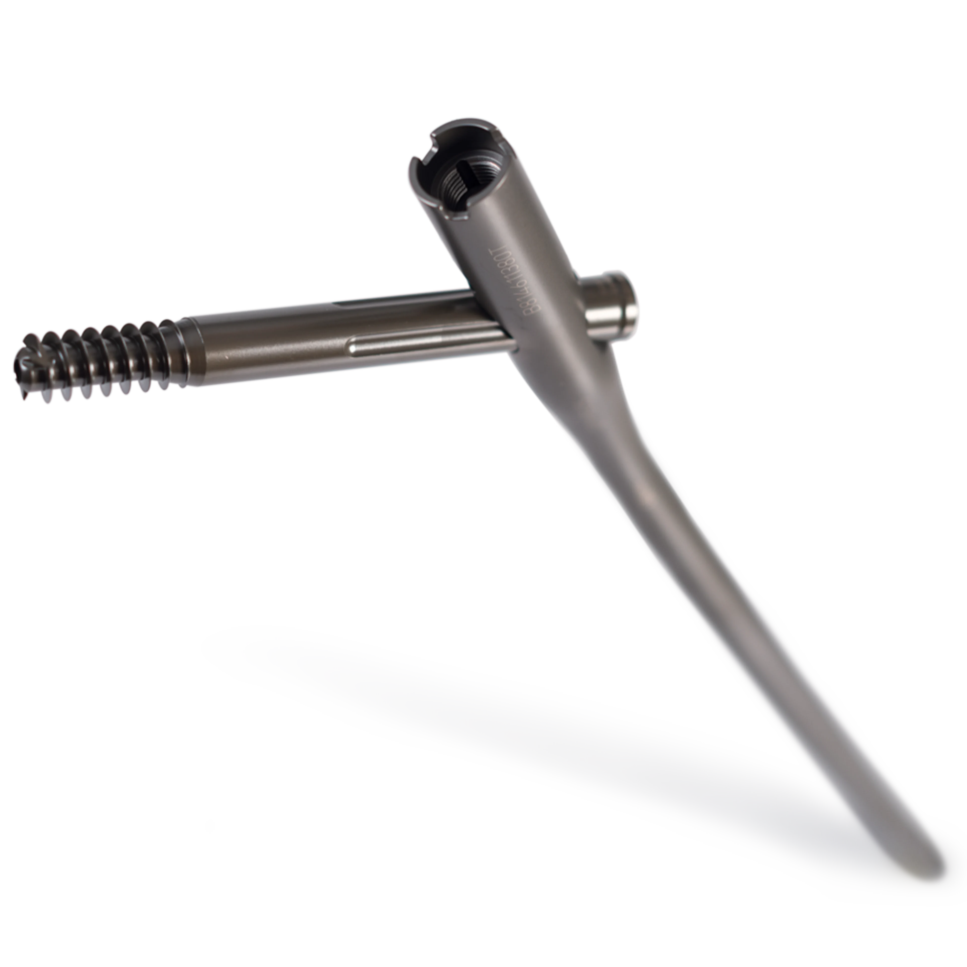
The system combines the principles of a compression hip screw with the biomechanical advantage of an intramedullary nail. By combining a proximal 1.8m radius of curvature with a 3° distal bend, the resultant bow is comparable to a proximal 1.5m radius of curvature with a minimal offset. This not only accommodates the anterior bow of the natural femur, but also is designed to help ease insertion through the proximal region and minimise the risk of penetrating the anterior cortex.
The GOAL POST Technology is designed to facilitate visualisation of the femoral neck on the lateral view in order to accurately place the guide pin for the lag screw. The anterior and posterior metal posts on the proximal aspect of the insertion jig allow for an unobstructed fluoroscopic view down to the base of the femoral neck and assist with fine turning of the guide pin before it is fully seated in the femoral head.
The nail is designed to include an anti-rotation (AR) hole, which can be used as a utility hole to provisionally stabilise a fractured femoral neck and head segment during the lag screw placement or for placement of an AR screw, if desired.
The lag screw was designed with a reverse buttress thread pattern, which is intended to provide subchondral support under load, while also helping minimize potential for "cut-off". The lag screw has wide slots or grooves providing the surgeon approximately 15° of adjustment when tightening the set screw. Also, the lag screw has a shoulder which is intended to prevent medial migration.
Since the system offers two different nail angles, 125° and 130°, it includes two easy-to-use jig assemblies that correspond to the neck angle of the implant. The jig assembly was also designed to include a jig tab. This jig tab mates with the implant nail slot to ensure both the targeting jig and implant neck shaft angle match. During use, if it is difficult to attach the nail to the jig assembly, it can simply be confirmed that the nail and jig assembly are identified with the same neck shaft angle.
On the proximal portion of the jig assembly, there are two holes, where a 3.2mm guide pin can be placed. Under lateral fluoroscopy, this guide pin gives a visual indication to the potential starting point of the 3.2mm guide pin.
When preparing the femoral canal, a flexible entry reamer has been designed to help with the entry on larger patients. This reamer will bend to help gain proper entry into the femoral canal. Also, flexibility has been added to the jig bolt driver. This allows the surgeon to easily tighten down the jig bolt inside the jig assembly.
This system includes a one piece compression wheel assembly that can be easily placed unto the lag screw driver by sliding the wheel device unto the lag screw driver without disassembling instrumentation. Rotate the compression wheel clockwise to compress the intertrochanteric components of the fracture.
The system comes with several useful reduction tools to aid in gaining proper alignment, length, and rotation. These tools are a ball spike pusher, bone hook, femoral bone clamp, pistol guidewire gripper, guidewire pusher and long reduction tool.
Optimal nail geometry with unique distal bend aid in placement of the implant within the femoral head and intramedullary canal.
Procedurally oriented tray layout with streamlined and colour-coded instruments to aid in procedural efficiency.
Extensive range of nail lengths and diameters targeting utility hole and revision option, offering the ability to customise the procedure.